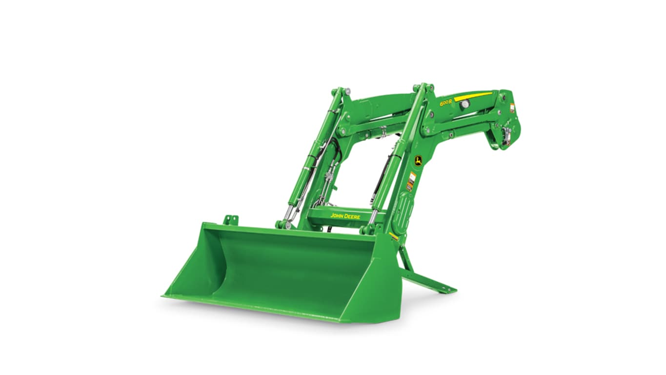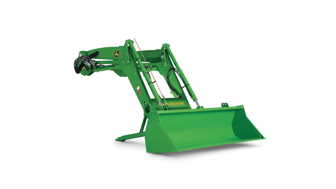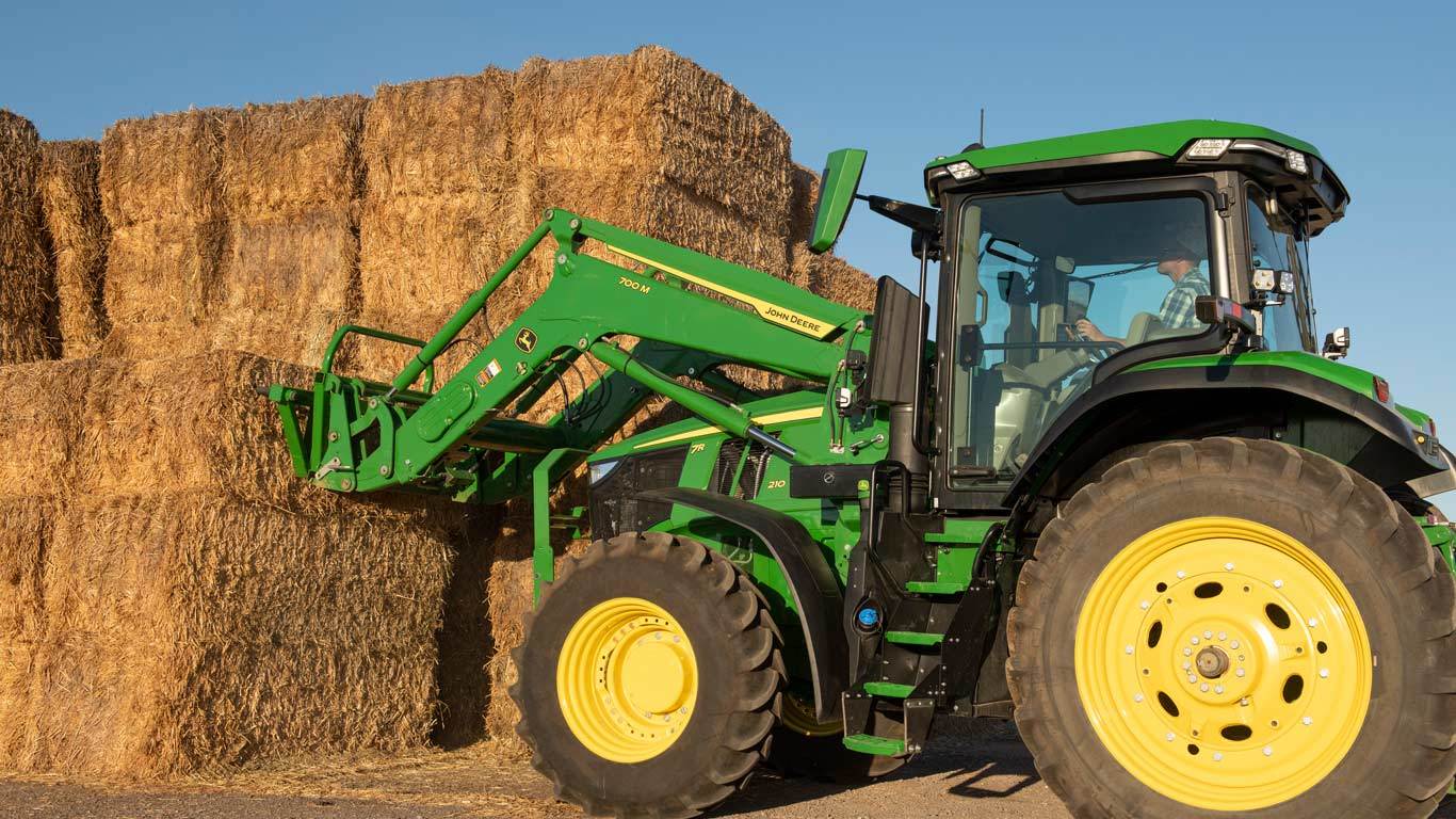
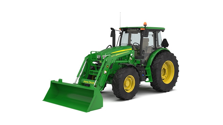
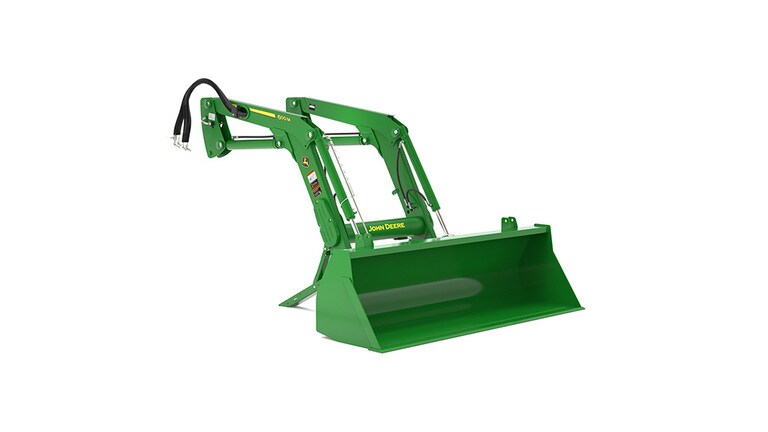


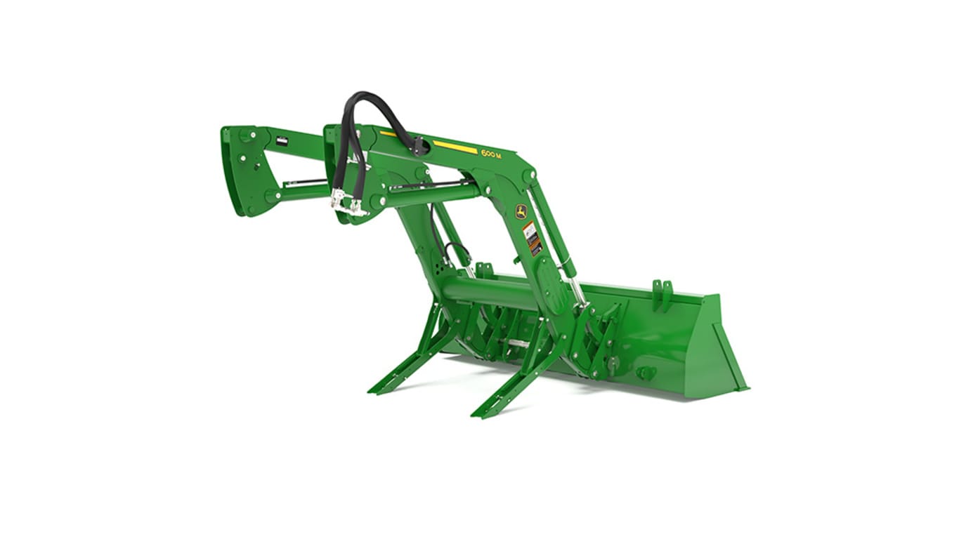
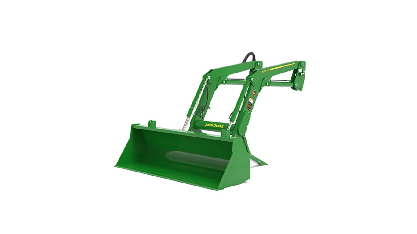
600MLoader
- Superior strength
- For heavy-duty chores
- Parking stands are integrated on the loader
- Mechanical self-leveling and non-self-leveling choices
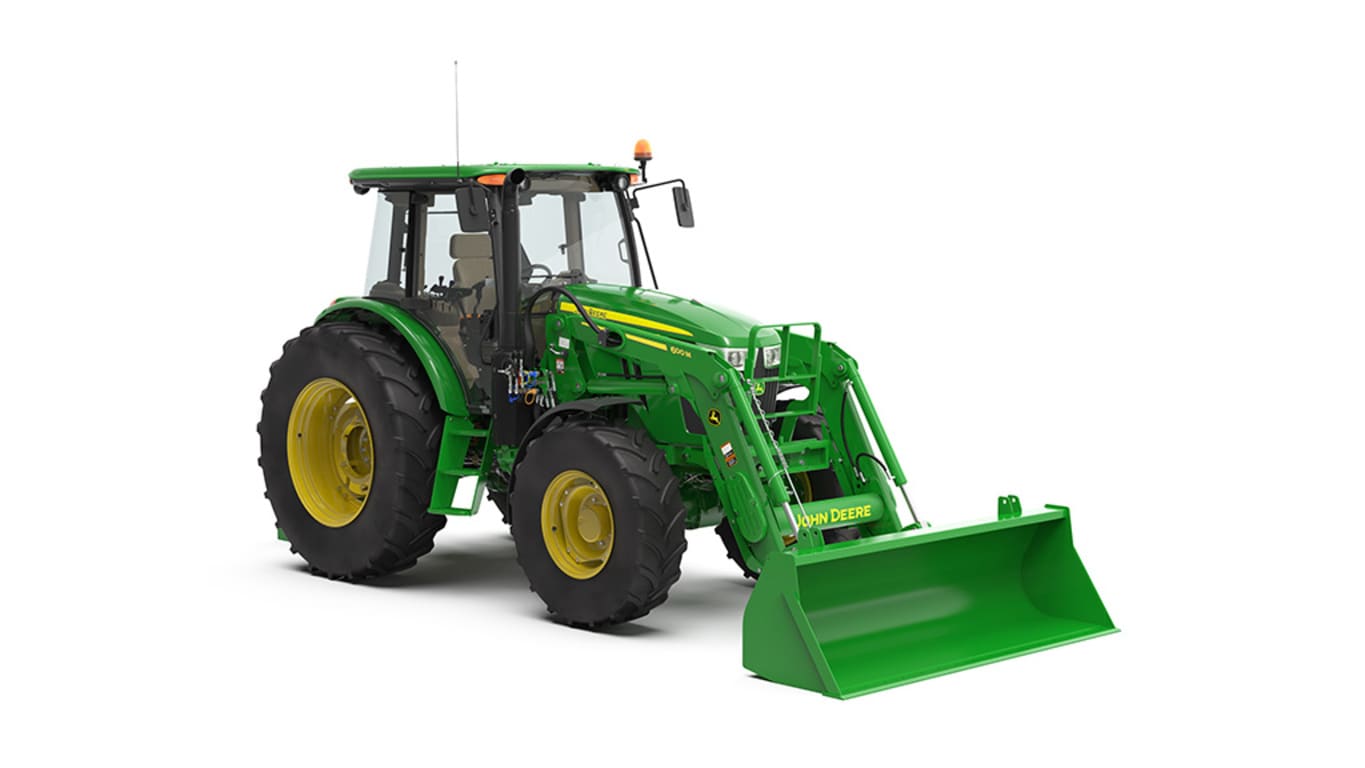


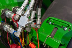
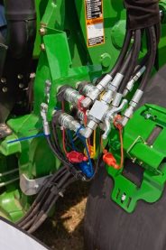
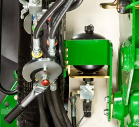
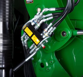
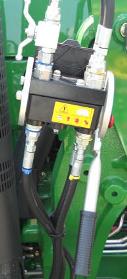
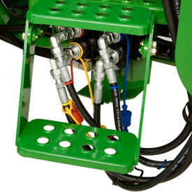
 Single-point hydraulic connection on 6 Series Tractors (closed position)
The 600M Loader can be ordered with a single-point hydraulic connection that also incorporates the connection point for any electrical needs. To disconnect the hydraulic connection between the loader and the tractor, it is necessary to relieve the hydraulic system oil pressure on the tractor.
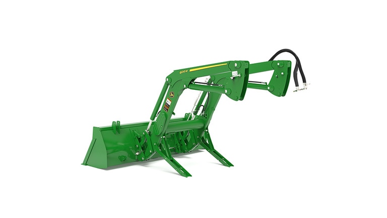
 Concealed oil lines through boom arm
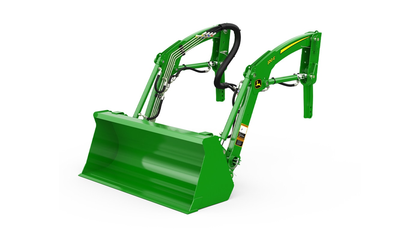
 Oil lines routed through the boom arm
 Oil lines routed through the torque tube
Over time, increased width in tractor hoods have caused issues with available space for running traditional oil lines of a loader along the boom, making them more susceptible to damage.
To improve this situation, the oil lines have been routed through the boom arm and the torque tube, improving line protection and the appearance of the loader.
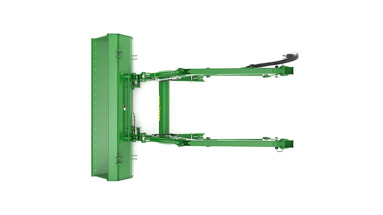
 Parking stands
John Deere loaders are easily removed and reinstalled on tractors without tools. The parking system allows removing or attaching the loader to the tractor in minutes without the need for tools.
To remove or park the loader, apply slight down pressure to the loader boom with the bucket dumped at approximately a 30-degree angle. With the tractor in park, lower the parking stands and place the mast pins in the open position.
 Parking stand in stored position
 Removing parking stand
 Mast pin in the closed position
 Rotating mast pin to the open position
Utilizing the boom circuit with the tractor in neutral, rotate the mast forward until the mast has rotated past the pin location on the mounting frame by extending the lift cylinder. Now using the bucket circuit, roll back the bucket until the mast is removed from the pocket and will clear the tires.
 Mast pin in the open position
With the tractor in park, shut the engine off and relieve the hydraulic pressure as indicated for the tractor (rotating the joystick). Disconnect or open the single-point hydraulic connector (or remove couplers if no single point is installed).
 Disconnect/open single-point hydraulic connection
 Disconnect/open single-point hydraulic connections
Store the loader half of the single-point connector or hoses, and back away from the loader.
 Single-point hydraulics disconnected
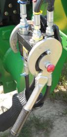
 Hydraulic shut-off valve (open position)
 Hydraulic shut-off valve (closed position)
A hydraulic shut-off valve is included with the M & R-Series Utility & Ag Loaders to ensure the loader does not lower suddenly. For example, this allows the boom to be locked out when someone is required to be located under the loader boom for service work on the tractor. It should not be used for extended periods of time unless an appropriate support stand is also utilized.
 False rod cylinder
Fast bucket cycle times are important to dump the load from the bucket as quickly as possible, in order to be as productive as possible, while completing loading operations. The bucket cylinder design can have a major impact on this cycle time, especially for the mechanical self-leveling (MSL) loaders.
Therefore, all MSL H-Series Loaders utilize false rod bucket cylinders. A false rod cylinder has a smaller displacement of oil requirement on the head end of the cylinder, which allows this cylinder to dump much faster than a normal cylinder.
| Specs & Compare | ||||
|---|---|---|---|---|
| Select up to 4 models to compare specifications | John Deere 600M Loader |
| Maximum lift height | ||||
|---|---|---|---|---|
| Lift capacity at full height | ||||
| Boom breakout force | ||||
| Bucket rollback force capacity | ||||
| Clearance at full height - bucket dumped | ||||
| Dump angle, degrees | ||||
| Rollback angle, degrees |
| Model | 6105D/6115D/6130D/6140D | |||
|---|---|---|---|---|
| Front tire | 14.9R24 | |||
| Rear tire | 18.4R38 | |||
| Front axle configuration | MFWD | |||
| Wheelbase | 2380 mm 93.7 in. |
|||
| Pump capacity | 76 L/min 20.1 gpm |
|||
| Rated pressure | 195 bar 2828 psi |
| Base weight | 1113.2 kg | |||
|---|---|---|---|---|
| Leveling configuration | Mechanical Self Leveling (MSL) | |||
| Bucket used | Materials 1850 mm Materials 73 in. |
|||
| Bucket weight | 281 kg 620 lb |
|||
| Lift capacity at full height | Measured at pivot 1646 kg 3629 lb Measured at 800 mm ahead of pivot 1790 kg 3946 lb |
|||
| Lift capacity at 59 in. (1500 mm) | Measured at pivot 2112 kg 4656 lb Measured at 800 mm ahead of pivot 2021 kg 4456 lb |
|||
| Boom breakout force | Measured at pivot 2583 kgf 5695 lbf Measured at 800 mm ahead of pivot 2259 kgf 4980 lbf |
|||
| Bucket rollback force capacity | At maximum height 1471 kgf 3243 lbf At 59-in. (1500-mm) lift height 2916 kgf 6429 lbf At ground-level line 2986 kgf 6583 lbf |
|||
| Dimensions | Maximum lift height 3830 mm 150.8 in. At full height - bucket level 3636 mm 143.1 in. At full height - bucket dumped 2801 mm 110.3 in. |
|||
| Overall length | 4.9 m 16.1 ft |
|||
| Overall height in carry position | ||||
| Digging depth | 56 mm 2.2 in. |
|||
| Reach | At maximum height 923 mm 36.3 in. At ground level - bucket level 2519 mm 99.2 in. |
|||
| Bucket angle | Dump angle, degrees -79 degree (angle) Rollback angle, degrees 43 degree (angle) Dump angle, ground -95 degree (angle) |
|||
| Cycle times | Loader raise, seconds 3.9 seconds Loader lower, seconds 2.9 seconds Bucket dump, seconds 2.1 seconds Bucket rollback, seconds 2.1 seconds |
| Date collected |
|---|
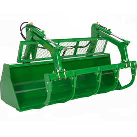
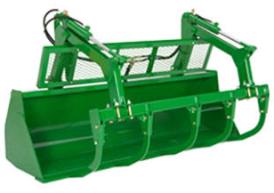 Heavy-duty bucket (shown with grapple)
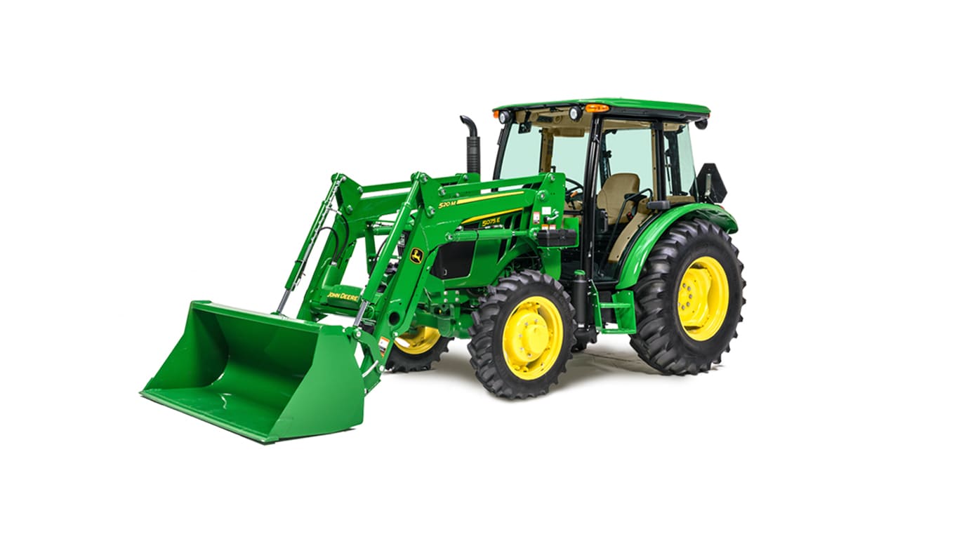
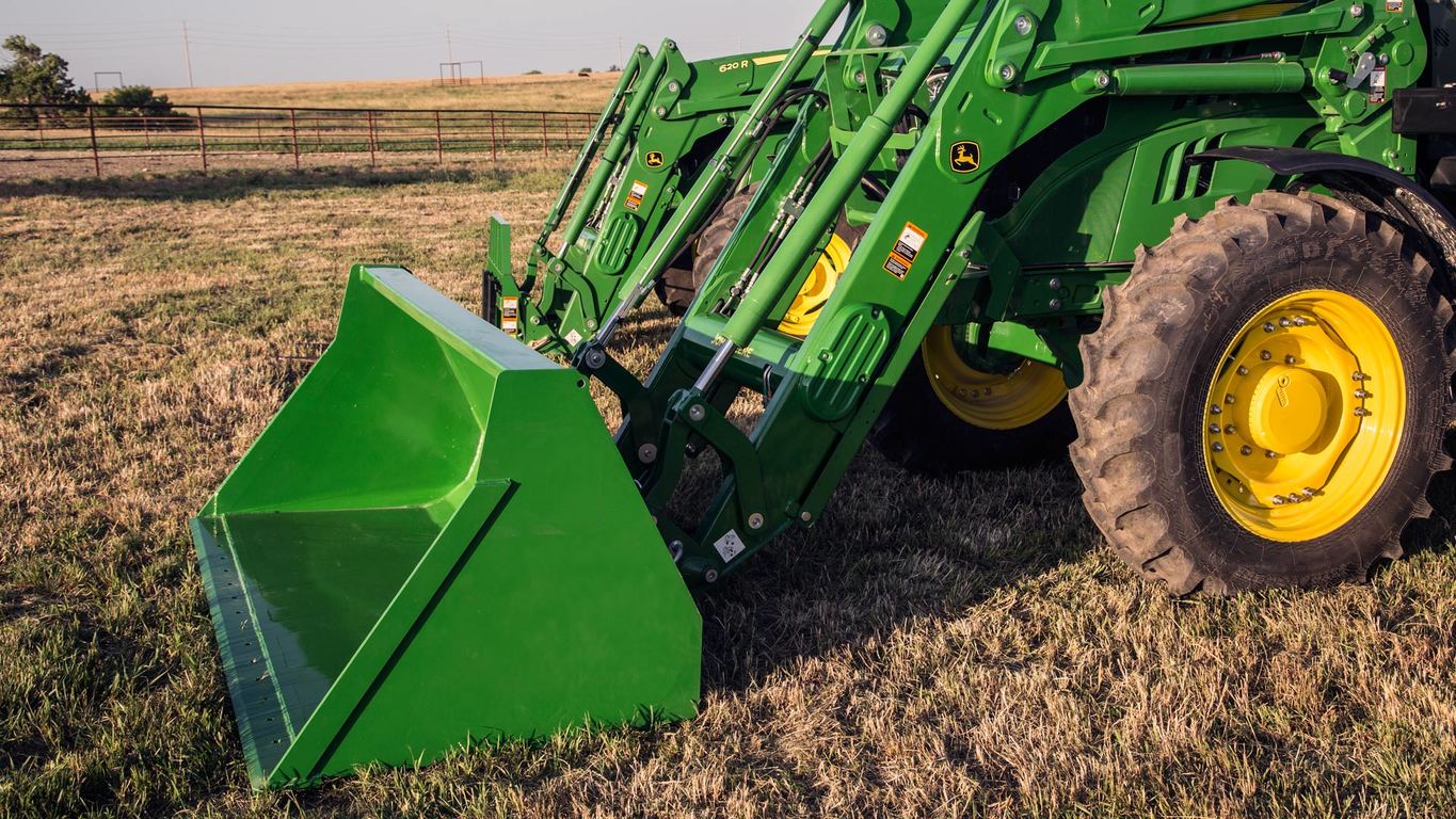
 Materials bucket
Materials buckets may be used for loading dirt, gravel, feed, and light materials as well as scraping, digging, and other general-purpose tasks.
NOTE: Materials buckets are not compatible with replaceable cutting edges or digging teeth.
Materials bucket
Materials buckets may be used for loading dirt, gravel, feed, and light materials as well as scraping, digging, and other general-purpose tasks.
NOTE: Materials buckets are not compatible with replaceable cutting edges or digging teeth.
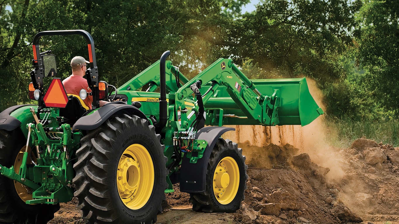
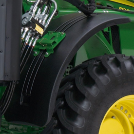 Stationary fender (H480 shown)
Loader stationary fenders are highly recommended for those operating in conditions where the front axle will be in full oscillation and turn frequently or where tight turns are made while maneuvering through gates or obstacles that will catch tractor axle-mounted fenders.
The loader stationary fenders still provide coverage for debris from the tire, but they do not protrude to become damaged in operation. The fenders can be removed to enable better access for servicing as well.
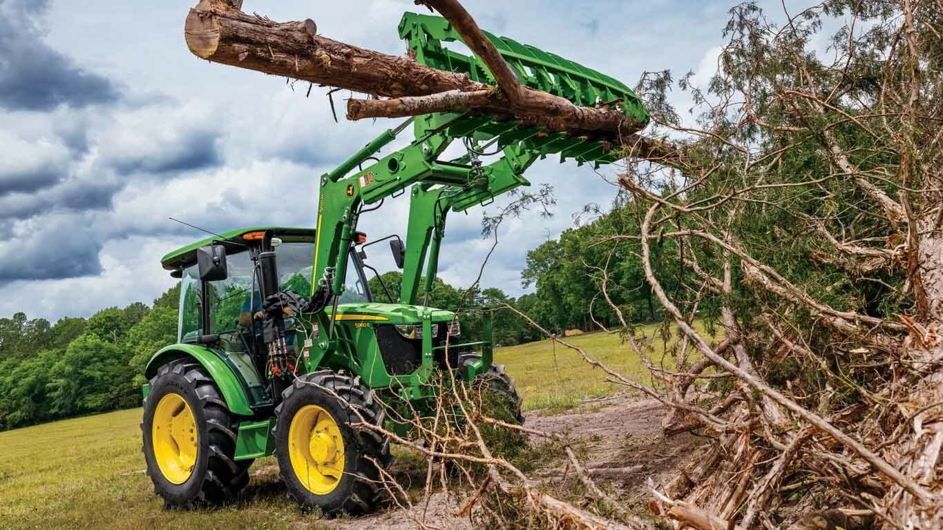
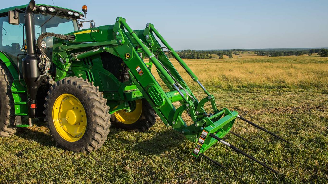
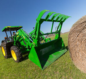
 Five-tine round bale/silage grapple with grille
All compatible John Deere Loaders use the same five-tine, pin-on grapple. The advantages of this grapple are:
High-performance operators will choose the five-tine grapple for its increased durability and load-carrying capacity. Advantages include:
The grapple is equipped with twin cylinders to provide excellent clamping force.
NOTE: The center tine of the five-tine grapple is slightly off center to avoid contact with the placement of optional digging teeth.
NOTE: The grapple is not compatible with materials or high-volume buckets.
 1850-mm (73-in.) bale grapple bucket
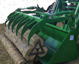 73–in. (1850 mm) grapple bucket BW15358 shown (all one piece
The bale grapple bucket is a complete solution ideal for full loads of silage, handling bales, or cleaning up debris or manure.
 Two function quick coupler
The H240, H260, H310, H340, and H360 Loaders feature two-function quick-couplers in base machine. To disconnect the hydraulic connection between the loader and the tractor, it is necessary to relieve the hydraulic system oil pressure on the tractor.
 Three function quick coupler
The H240, H260, H310, H340, and H360 Loaders can be equipped with three-function quick-couplers. Hoses will be installed in the boom arm and just the couplers will need to be assembled along with the third-function bracket and oil line. To disconnect the hydraulic connection between the loader and the tractor, it is necessary to relieve the hydraulic system oil pressure on the tractor.
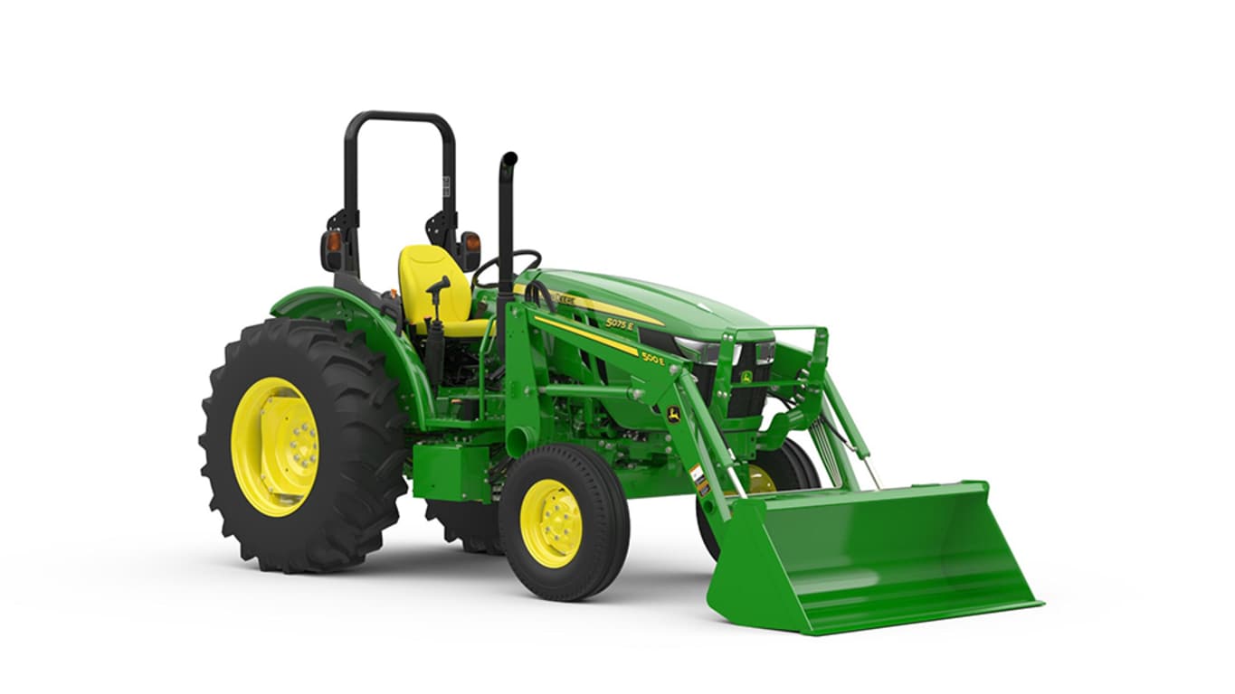
 Hood guard on 5100E Tractor

The hood guard’s basic function is to:
It is highly recommended to purchase a front weight bracket when using a loader. The hood guard is designed to be slightly rearward of the front weight. This is so that the front weight is the first point of contact against lower stationary objects.
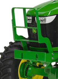
 Hood guard for 5E 4-cylinder and 5M Series Tractors
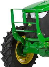
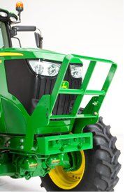
 Hood guard for 6D and 6E Series Tractors
The heavy-duty hood guard is compatible with 5E 4-cylinder, 5M, 6D, and 6E Tractors.
NOTE: See below for details on tractor family, series, and model years.
The basic function of a hood guard is to:
The hood guard:
It is highly recommended to purchase a front weight bracket when using a loader. The hood guard is designed to be slightly rearward of the front weight bracket. This is so the front weight bracket is the first point of contact against lower stationary objects.
If a front weight bracket is not used, the lower bar can be moved downward to improve the protection of the grille below the lights.
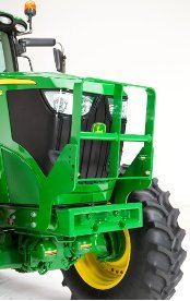
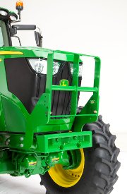 Hood guard on 6R Tractor
 Hood guard for 6R folded down
The hood guard's basic function is to:
Compatibility:
It is highly recommended to purchase a front weight bracket when using a loader. The hood guard is designed to be slightly rearward of the front weight bracket. This is so the front weight bracket is the first point of contact against lower stationary objects. The height of the hood guard allows better protection for the top of the hood and allows operators to see the top of the hood guard.
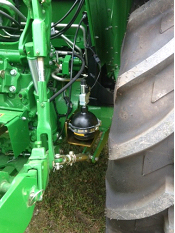
 Nitrogen-charged accumulator and electric valve
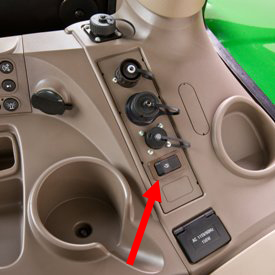 Operator on/off switch
 LSS on H180
 LSS on 5E and 5M
An enhancement to the loader is the suspension system. A great level of loader productivity is achieved with the LSS.
Performance
NOTE: Check bale-handling capability of tractor before use.
Cost of ownership
Reasons for turning LSS off include:
The switch is conveniently located in the operator station to avoid having to exit the tractor seat to manually move the handle on the LSS.
LSS can also be ordered with a manual shutoff. Depending on the tractor/loader model, the accumulator is located in different places. On the 440R, the accumulator is mounted outside the bottom of the mounting frame. On the 5 Series Tractors, the accumulator is mounted near the inside of the rear right wheel. On 6 Series tractors and larger, it is mounted in between the hydraulic connection and the mounting frame.
Stationary fender (H480 shown)
Loader stationary fenders are highly recommended for those operating in conditions where the front axle will be in full oscillation and turn frequently or where tight turns are made while maneuvering through gates or obstacles that will catch tractor axle-mounted fenders.
The loader stationary fenders still provide coverage for debris from the tire, but they do not protrude to become damaged in operation. The fenders can be removed to enable better access for servicing as well.
Nitrogen-charged accumulator and electric valve
Operator on/off switch
LSS on H180
LSS on 5E and 5M
An enhancement to the loader is the suspension system. A great level of loader productivity is achieved with the LSS.
Performance
NOTE: Check bale-handling capability of tractor before use.
Cost of ownership
Reasons for turning LSS off include:
The switch is conveniently located in the operator station to avoid having to exit the tractor seat to manually move the handle on the LSS.
LSS can also be ordered with a manual shutoff. Depending on the tractor/loader model, the accumulator is located in different places. On the 440R, the accumulator is mounted outside the bottom of the mounting frame. On the 5 Series Tractors, the accumulator is mounted near the inside of the rear right wheel. On 6 Series tractors and larger, it is mounted in between the hydraulic connection and the mounting frame.
Two function quick coupler
The H240, H260, H310, H340, and H360 Loaders feature two-function quick-couplers in base machine. To disconnect the hydraulic connection between the loader and the tractor, it is necessary to relieve the hydraulic system oil pressure on the tractor.
Three function quick coupler
The H240, H260, H310, H340, and H360 Loaders can be equipped with three-function quick-couplers. Hoses will be installed in the boom arm and just the couplers will need to be assembled along with the third-function bracket and oil line. To disconnect the hydraulic connection between the loader and the tractor, it is necessary to relieve the hydraulic system oil pressure on the tractor.
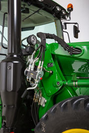
 Single-point hydraulic connection on row crop tractor
 Single-point hydraulic connection on 5E Series Tractor
 Single-point hydraulic connection on 5M Series Tractor
 Single-point hydraulic connection with rigid lines on FT4 6R large frame
The H240, H260, H310, H340, and H360 Loaders feature a single-point hydraulic connection that also incorporates the connection point for any electrical needs as well. To disconnect the hydraulic connection between the loader and the tractor, it is necessary to relieve the hydraulic system oil pressure on the tractor.
Single-point hydraulic connection on row crop tractor
Single-point hydraulic connection on 5E Series Tractor
Single-point hydraulic connection on 5M Series Tractor
Single-point hydraulic connection with rigid lines on FT4 6R large frame
The H240, H260, H310, H340, and H360 Loaders feature a single-point hydraulic connection that also incorporates the connection point for any electrical needs as well. To disconnect the hydraulic connection between the loader and the tractor, it is necessary to relieve the hydraulic system oil pressure on the tractor.
 Replaceable wear edge
For those who frequently scrape on concrete, a replaceable cutting edge will greatly extend the life of the bucket:
Two function quick coupler
The H240, H260, H310, H340, and H360 Loaders feature two-function quick-couplers in base machine. To disconnect the hydraulic connection between the loader and the tractor, it is necessary to relieve the hydraulic system oil pressure on the tractor.
Three function quick coupler
The H240, H260, H310, H340, and H360 Loaders can be equipped with three-function quick-couplers. Hoses will be installed in the boom arm and just the couplers will need to be assembled along with the third-function bracket and oil line. To disconnect the hydraulic connection between the loader and the tractor, it is necessary to relieve the hydraulic system oil pressure on the tractor.
Single-point hydraulic connection on row crop tractor
Single-point hydraulic connection on 5E Series Tractor
Single-point hydraulic connection on 5M Series Tractor
Single-point hydraulic connection with rigid lines on FT4 6R large frame
The H240, H260, H310, H340, and H360 Loaders feature a single-point hydraulic connection that also incorporates the connection point for any electrical needs as well. To disconnect the hydraulic connection between the loader and the tractor, it is necessary to relieve the hydraulic system oil pressure on the tractor.
 Hood guard on 6R Tractor
 Hood guard for 6R folded down
The hood guard's basic function is to:
Compatibility:
It is highly recommended to purchase a front weight bracket when using a loader. The hood guard is designed to be slightly rearward of the front weight bracket. This is so the front weight bracket is the first point of contact against lower stationary objects. The height of the hood guard allows better protection for the top of the hood and allows operators to see the top of the hood guard.
Hood guard for 5E 4-cylinder and 5M Series Tractors
Hood guard for 6D and 6E Series Tractors
The heavy-duty hood guard is compatible with 5E 4-cylinder, 5M, 6D, and 6E Tractors.
NOTE: See below for details on tractor family, series, and model years.
The basic function of a hood guard is to:
The hood guard:
It is highly recommended to purchase a front weight bracket when using a loader. The hood guard is designed to be slightly rearward of the front weight bracket. This is so the front weight bracket is the first point of contact against lower stationary objects.
If a front weight bracket is not used, the lower bar can be moved downward to improve the protection of the grille below the lights.
 2-function hoses and couplers
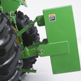
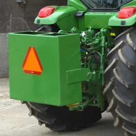
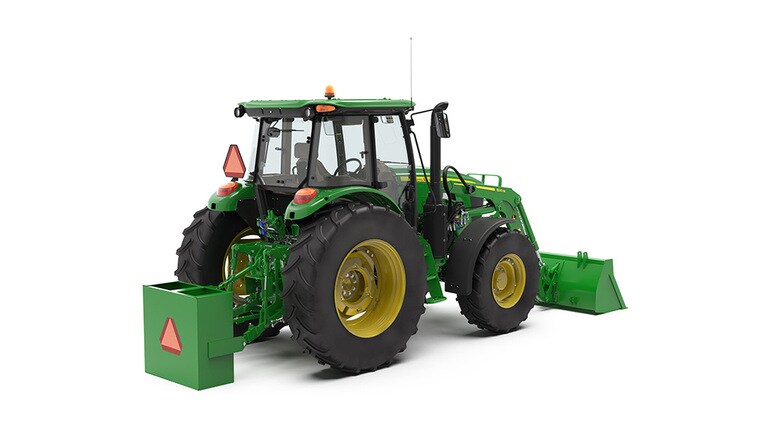
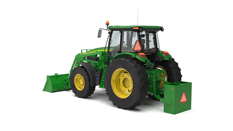
Large ballast box is available to carry additional ballast for greater tractor stability.
Capacities |
|||
Weight |
Sand (Dry) |
Concrete |
Portland Cement |
BW15852 Large ballast box: |
|||
| Volume | 13.3 ft3 = 377L |
||
Material |
581 kg (1277 lb) |
871 kg (1915 lb) |
1089 kg (2395 lb) |
Empty box |
155 kg (342 lb) |
155 kg (342 lb) |
155 kg (342 lb) |
Total |
736 kg (1619 lb) |
1026 kg (2257 lb) |
1244 kg (2737 lb) |
BW15852 Large ballast box is compatible with Category 2 Quik-Couplers and Category 2 or 3 hitches.
See ''Rear Ballast Requirements'' for proper ballasting of the tractor.
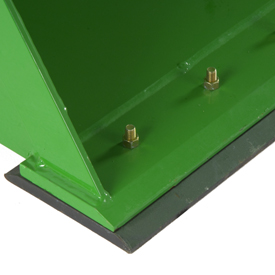
 5M mounting frame
 5M mounting frame
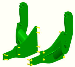
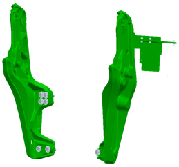 6E Final Tier 4 (FT4) and 6D Interim Tier 4 (IT4) (model year 2013-2015) mounting frame
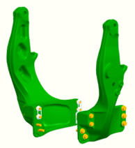
 6D (model year 2012 and prior) mounting frame
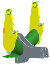
 6M (small chassis), 6R (small chassis), 6030, 6030 Premium, 6020, 6010, and 6000 Series Tractors mounting frame
 5E 4 Cylinder (IT4; 5085E, 5100E) mounting frame
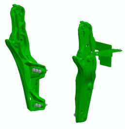
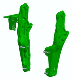
Mounting frames are designed to evenly distribute forces during loader operation. Hardware is accessible to torque to the correct specifications.
5M mounting frame
5M mounting frame
6E Final Tier 4 (FT4) and 6D Interim Tier 4 (IT4) (model year 2013-2015) mounting frame
6D (model year 2012 and prior) mounting frame
6M (small chassis), 6R (small chassis), 6030, 6030 Premium, 6020, 6010, and 6000 Series Tractors mounting frame
5E 4 Cylinder (IT4; 5085E, 5100E) mounting frame
Mounting frames are designed to evenly distribute forces during loader operation. Hardware is accessible to torque to the correct specifications.
Images of equipment models may be digitally or AI generated, are for illustration purposes only, and are subject to change. Equipment models shown are typically base models and may not reflect the actual product, features, options, or attachments. Equipment availability may be limited. See your John Deere dealer for additional information.